Home / Shop
Firing Device, Pull/Release, M3


- Description
- Specifications
In February of 1943 Mr. Roysdon of the Engineer Board asked the A. C. Gilbert Company to design a pull firing device that would also fire on release of tension on the trip wire. The company designed the T3 Pull Release firing device, later standardized as the “Firing Device, Pull/Release, M3”. The first order for 1000 devices was then issued to the company on 3 August 1943.
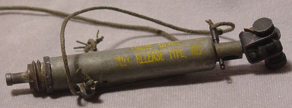
The device consists of several parts, the body, ratchet mechanism, striker and striker spring and retaining rod. The body is cast of zinc alloy in a cylindrical form and has a lug on the side for the anchor cord. At the top of the body a reduced diameter head is crimped in that has an elongated safety pin hole in it. The bottom of the body is internally threaded to accept the base coupler. Internally the body has a constriction about ¼ the way down from the top. The ratchet mechanism is loosely attached to the retaining rod. The retaining rod has a head formed at the bottom end and is long enough to fit slightly through the constriction in the body. The striker is made with a striker head at the bottom, a shaft and slightly wider head at the upper end. The striker is split to form four jaws at the top end. The safety pin is made with a reduced diameter in the centre.
The body of the device is either painted olive green or has a green wash applied. The ratchet assembly is black. Markings are in yellow giving the designation of the device.
When assembled, the striker and striker spring are forced up from the bottom of the body until the top of the striker fits through the constriction and engages the head on the retaining rod. The safety pin is placed through the elongated hole and retaining rod which keeps the striker from passing fully through the constriction under pressure of the spring. With the top of the striker held at the constriction, the jaws cannot open enough to release the head on the retaining rod. A positive safety pin is then placed through holes in the side of the body below the striker head.
When laid, the device is fixed in position with the anchor cord and a trip wire attached to the ratchet mechanism. The wire is then tensioned until the safety pin is about in the middle of the elongated hole. The safety pin can then be removed and the positive safety pin removed last. The wire is taut and when a pressure of 6-10 pounds is applied to the wire it will pull the retaining rod and striker up through the constriction until the jaws on the striker can open enough to release the retaining rod. The striker is then free to move down under pressure from the spring to strike the percussion cap in the base coupler. Alternatively, if the wire is cut or removed the striker spring will apply pressure to move the striker and retaining rod down through the constriction until the jaws can open and release the striker to move down under pressure of the spring to hit the percussion cap in the base coupler.