Home / Shop
Firing Device, Pressure, M1 New style (WWII Issue)


- Description
- Specifications
Firing Device, Pressure, M1 New style (WWII Issue)
The A. C. Gilbert Co. in collaboration with the Engineer Board, redesigned the firing device in August 1942 so that it could be made from die cast zinc alloy. This change simplified production, saved critical brass, include a positive safety and reduced the weight of the device. It was adopted in mid-1943 to replace the old style. The first contract for this version was for 685,000 firing devices.
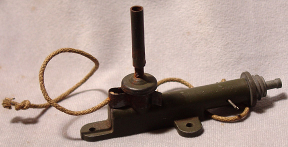
The device consists of a body, pressure head and base coupler. The body is die cast zinc alloy made in a single piece. It has a basically tubular body with a flattened base for about half the length. Protruding out from the base are three lugs that are used to fasten the device in place. A hole in the top of the body fits the pressure head. The striker which has a firing pin head at one end and a groove in the shaft at the other fits with the striker spring inside the body. The pressure head has a flat top with a shaft on the bottom. There is a keyhole in the lower portion of the shaft. The base coupler is the standard M1 base coupler.
When assembled, the striker and spring are put into the body and forced into the body so that the shaft of the striker fits into a small hole in the back that connects with the hole in the top of the body. The pressure head with spring are pushed down so the shaft of the striker fits through the large upper hole in the keyhole. Once the shaft of the striker is pushed through the pressure head is released so that the small portion of the keyhole engages in the groove in the striker shaft. This holds the striker back in the cocked position. A safety clip fits over the spring on the pressure head preventing its downward movement. A positive safety pin is fitted through holes in the side of the body in front of the striker.
The device is supplied with an extension rod. The rod consists of a length of threaded rod mounted on a cup and an internally threaded tube. The cup press fits onto the pressure head. The extension provides between 1.25 and 2.25 inches of extension.
When laid and the safety pin and clip are removed, a pressure of 20 pounds or more will cause the pressure head to move down bringing the large end of the keyhole in line with the striker shaft disengaging it from the striker groove. This allows the striker spring to reassert itself and push the striker forward until it strikes the percussion cap in the base coupler. The cap fires and initiates the detonator attached to the base coupler and in turn the main charge.
The A. C. Gilbert Co. in collaboration with the Engineer Board, redesigned the firing device in August 1942 so that it could be made from die cast zinc alloy. This change simplified production, saved critical brass, include a positive safety and reduced the weight of the device. It was adopted in mid-1943 to replace the old style. The first contract for this version was for 685,000 firing devices.
The device consists of a body, pressure head and base coupler. The body is die cast zinc alloy made in a single piece. It has a basically tubular body with a flattened base for about half the length. Protruding out from the base are three lugs that are used to fasten the device in place. A hole in the top of the body fits the pressure head. The striker which has a firing pin head at one end and a groove in the shaft at the other fits with the striker spring inside the body. The pressure head has a flat top with a shaft on the bottom. There is a keyhole in the lower portion of the shaft. The base coupler is the standard M1 base coupler.
When assembled, the striker and spring are put into the body and forced into the body so that the shaft of the striker fits into a small hole in the back that connects with the hole in the top of the body. The pressure head with spring are pushed down so the shaft of the striker fits through the large upper hole in the keyhole. Once the shaft of the striker is pushed through the pressure head is released so that the small portion of the keyhole engages in the groove in the striker shaft. This holds the striker back in the cocked position. A safety clip fits over the spring on the pressure head preventing its downward movement. A positive safety pin is fitted through holes in the side of the body in front of the striker.
The device is supplied with an extension rod. The rod consists of a length of threaded rod mounted on a cup and an internally threaded tube. The cup press fits onto the pressure head. The extension provides between 1.25 and 2.25 inches of extension.
When laid and the safety pin and clip are removed, a pressure of 20 pounds or more will cause the pressure head to move down bringing the large end of the keyhole in line with the striker shaft disengaging it from the striker groove. This allows the striker spring to reassert itself and push the striker forward until it strikes the percussion cap in the base coupler. The cap fires and initiates the detonator attached to the base coupler and in turn the main charge.